
RGB Photoflood - An Arduino Project

RGB LED Photoflood

Links to code and video at the bottom of this article

So, I was looking at the price of photo floods for photography and video production and baulking at the prices. I had previously used a battery powered one with 160 LEDs that cost around 20 GBP which was ok for basic photography lighting fill-in, that is to supplement room lighting. But for video you really need something more powerful. So my criteria was 


  • Must be mains powered

  • Must be RGB programmable for effects

  • Optional - can display scrolling messages

  • Must stand prolonged usage

  • Cheap enough to make several to provide multiple light sources, possible with differing tints.

  • Easy to construct and copy.


Common sense and available components said it should be Arduino based because


  • I have a drawer full (or did)

  • There are many variants as cheap as 3 GBP + postage and packing in multiple pack purchase

  • They are easy to program and have simple power needs, i.e. 5 volts the same as WS2812 LEDs


I have seen WS2812 256 LED programmable matrixes sold for as much as 70 GBP which makes me baulk! But a bit of research and some special offers on Ebay (other sources are available) had myself and my partner ordering one each on top of the one I already had sourced and tested some simple programs on. Now these are generally designed to have patterns, words and graphics displayed on them and I did buy a 8 GBP controller which can operate form a mobile phone and made some pretty patterns on one. I had heard a few people say that you should not run these 100% on all LEDs and it is also mentioned that the LEDs can become de-flowed, that is desoldered. Well you have been warned and the hobbyist is likely to be capable or soldering a few joints in the even of a problem.  I think this will put out 5 Volts x 7 Amps = 35 Watts. Probably equivalent to 150 watts of incandescent lighting but with RGB control!


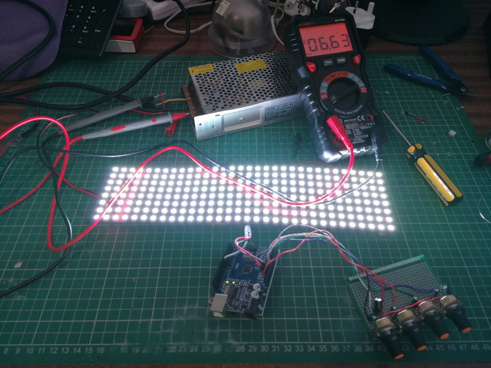
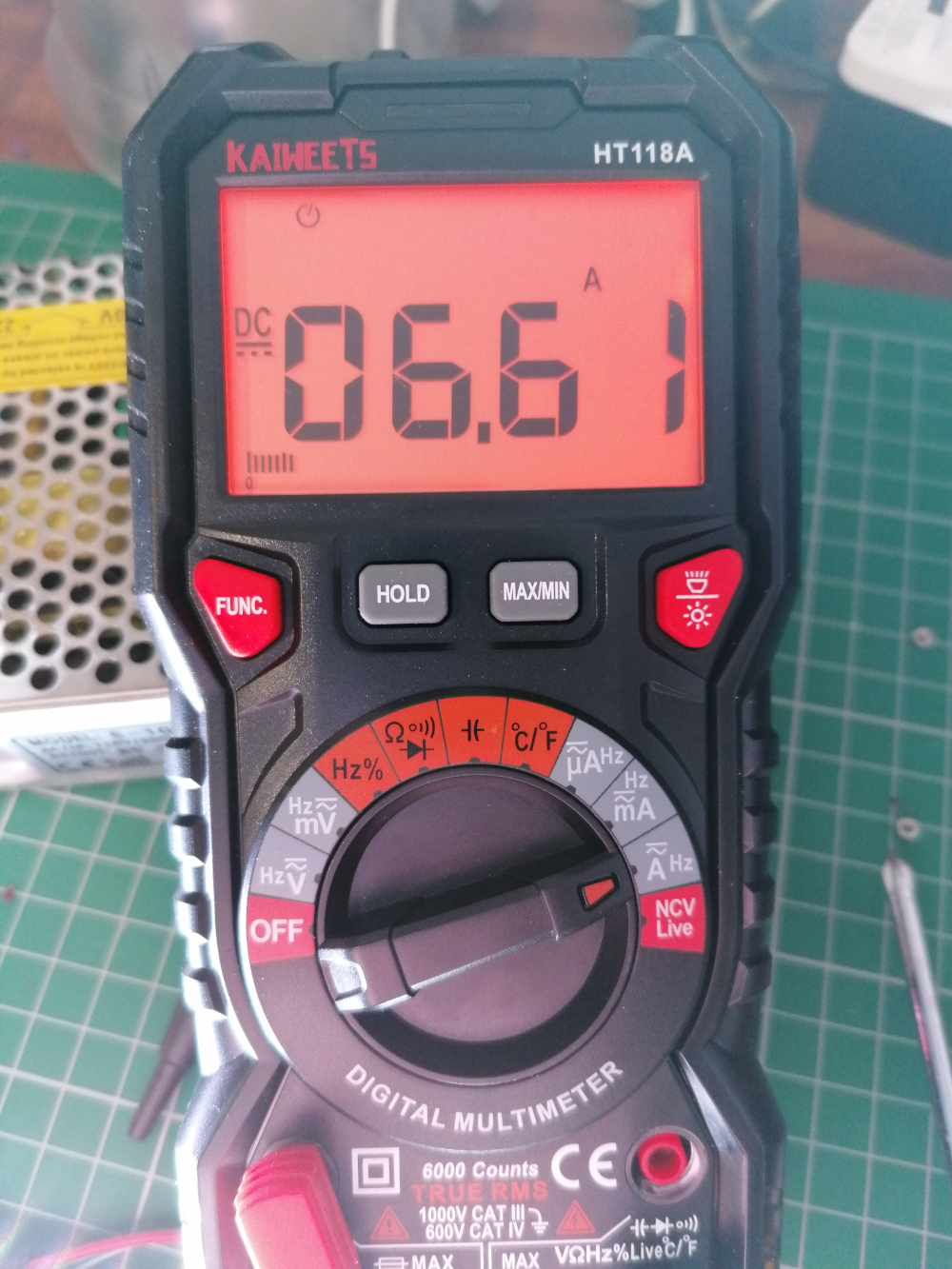
As for cooling I will be installing a PC cooling fan in each box. I reckon they consume 6.7 amps when fully on. You will need substantial wire from the 5V power supply to the LEDs as I managed to almost melt mine when trying to drive 3 LED matrixes at once!


The circuit was proved using an Arduino UNO on breadboard and I initially mounted the controls and resistors on prototyping board, even though this was only a half sheet i knew I had enough space for an Arduino Nano or Arduino Every. The Every is pin compatible and available in three packs, well I did want to build three of these so I ordered them from Ardiono.cc


The completed circuit board


Not too many connections to the Arduino Every

The underside view


I used the component's legs to make the bridges between the dots, this helps to avoid using large blobs of solder which can short circuit between tracks.


The assembled electronics. Use extreme caution with testing using mains voltages, it can be lethal. I will add a mains switch and 1 amp fuse and fuse holder and build it all into a box for safety.


Parts List (Amazon links are associate links for which I earn a small commission, you pay no extra at all)

R1-4 100K linear potentiometer https://amzn.to/34udyM9

R5-9 10k 1/4 carbon resistor https://amzn.to/3p7vLXU

IC1 Arduino Nano or Every https://store.arduino.cc/arduino-nano-every

1 x PCB or prototype board https://amzn.to/2WwvGAL

PB1 momentary contact push button https://amzn.to/2KlTGUO

USB lead to program Arduino

Assorted cable


Code on GitHub https://github.com/TekMaker/arduino_projects, just click download as zip or clone if you have Git.


YouTube video and instructions to modify code https://www.youtube.com/watch?v=_oBho88mrvk&list=PLD8LpUarTkkYW0hYQ8hFyVJ1XqDnbblBH


Comments

Popular posts from this blog

Setting up a PI-Star MMDVM hotspot node with a Raspberry PI

 The first thing is to download the Pi-Star software from https://www.pistar.uk/downloads/ , at time of writing the current version is Pi-Star_RPi_V4.1.5_21-Jun-2021.zip ,but you should get the latest available. I used a Raspberry PI 3B but it is possible to use a PI Zero W or other model. You should then use either Etcher, or the Raspberry Pi imager to copy the image to your SD card, which should be at least 4GB and Class 10 or better, I used a 16GB simply because they are available for little money these days. Simply put the SD card into your PI and attach a monitor and keyboard via USB connection. The PI should boot with the usual rainbow screen, the default login is pi-star and the password raspberry. We will change these soon. To find out what IP address your pi is on type ifconfig and hit return. If you are connected via ethernet you will be able to type http://pi-star.local into a browser and access the dashboard as below - This will redirect after 10 seconds and you will be pre

Baofeng UV-S9 - a practical user guide

Having bought one of these transceivers recently I was firstly disappointed in the User Manual, it is in extremely small print, barely 4 point and my first searches online brought a pdf of the same manual scanned badly which was not much of an improvement. Also it is a reference guide rather than a how-to. I think many people would prefer to learn how to use the radio as well as which buttons to press with context. I am only covering the basics as I think once you know those then you will figure out the rest using the two manuals I have linked to below. So here we go! The Baofeng UV-S9 Transceiver, around £25 on Ebay Caution, two things are very important to know before we begin. Firstly it is illegal to transmit on any band that you do not hold a license for. You must check with your licencing authority, which in the UK is Ofcom https://www.ofcom.org.uk. PMR446 is not currently legal for a radio which does not have a fixed antenna and it is illegal to use a Baofeng for this purpose. A

Xiegu G1M - FT8 and CAT control imcompatibility

 So, having set up WSJT-X and made up cables for the Xiegu G1M I did manage to make a couple of contacts, well four to be exact I had difficulty keeping Transmit mode open and there was some weird VFO A-B switching and delays happening. I was starting to get pissed off.  I had been using the WSJT-X config set up Icom IC-7000 and IC-765 Pro as other people where doing the same, not very satisfactory and very frustrating. After much digging I managed to find out more info on the Xiegu forum at https://groups.io/g/XIEGU-G1M/message/461 . Seems that FLRIG was more suitable that the built in controller in WSJT-X, so I downloaded it from  http://www.w1hkj.com/  and installed it prior to running WSJT-X. After an hour or more of trying other peoples recommendations of Icoms and other rigs I started afresh. To control a Xiegu we need Xiegu thinking. Of course the G1M isn't listed in the devices yet, but the G90 is. Surely we could make that work as most manufacturers use a specific chip in